


Achievements
ARTIFICIAL RECHARGE OF GROUNDWATER IN THE UPPER CATCHEMENT AREA OF KUMARI RIVER BASIN, INDIA
R.P.Singh, Sangita
Dey and G.K.Rajan Department of Geology Banaras Hindu
Univwesity.Varanasi-221005,
Abstract:Artificial recharge of groundwater involves augment of the movement of surface water into groundwater formations by some methods of construction. Artificial groundwater recharge is becoming increasingly necessary as growing population require more water and as more stores is needed to save water in times of surplus for use in time of shortage. The present investigation of artificial recharge of groundwater in the upper catchments area of the Kumari river basin has been carried out in an area by latitude 220-55’-230-15’ N and longitude 860-08’ -860-38’E situated in the western part of the Purulia District, West Bengal. The Kumari River is the main tributary of the Kasai river that is finally drains its water into the Bay of Bengal. Rain and snow being the primary renewable source of water and rain water harvesting viewed in wider prospective forms the primary source of water for artificial groundwater recharge .The wider prospective of rain water harvesting includes water from perennial or ephemeral streams regulated with dams , storm runoff including that of urban areas, ponds and lakes . Infact any source of surplus water directly originated from snow or rain. The other sources of recharge water may originate from aqueducts or other water conveyance facilities, irrigation areas, drinking water treatment plants and sewage water treatment plants. Artificial recharge of groundwater is expected to play an increasing role in reuse of wastewater because movement of water through soils and aquifers provides a means of geo-purification of water through the process known as Soil –Aquifer-Treatment (SAT).
Key words: - Artificial recharge, Groundwater, Aquifer, River basin,Surface water, Vadose zone, Infiltration, Sewage water,
Introduction:
Many parts of
Geology and Climate of the Area:
The area forms a part of the southeastern extension of Chhotanagpur
plateau in eastern
Source of Water For Artificial Recharge:
Rain and snow being the primary renewable sources of water, rain water harvesting, viewed in a wider perspective, forms the primary source of water for artificial ground water recharge. This wider perspective of rainwater harvesting includes water from perennial or ephemeral streams regulated with dams, storm runoff, including that of urban areas, ponds and lakes; in fact any source of surplus water directly originated from snow/rain. Other sources of recharge water may originate from aqueducts or other water conveyance facilities, irrigation areas; drinking water treatment plants and sewages water treatment plants. Artificial recharge of groundwater is expected to play an increasing role in reuse of waste water , because movement of water through soils and aquifers provides a means of “geo-purification” of water through the process known as Soil-Aquifer-Treatment(SAT)(fig.2). Recharge also makes reuse of wastewater more acceptable by removing the connotation of “unclean” wastewater, where renovated municipal wastewater is used to augment water supplies.
Artificial Recharge Methods & Structure
Surface infiltration
Infiltration systems for artificial groundwater recharge are designed to increase downward infiltration of water at rates significantly higher than that of natural water input into the soil (precipitation and infiltration from fields and bare soil), streams, ponds, lakes or other natural water bodies. This is achieved by: 1) increasing the wetted area/duration and head over the infiltration surface and /or, 2) removing the low permeability soil layer where possible. Surface infiltration structures may be broadly divided into “In-channel” and “Off-channel” structure. ‘In-channel’ structures are associated with the Stream-Channel method and Ditch and Furrow methods. ‘In-channel’ structures consist of dams placed across ephemeral, or perennial, streams to back the water up and spread it out, thus increasing the wetted area of the stream bed or flood plain so that more water infiltrates into the ground.
Stream Channel Method:
Water spreading in a natural stream channel involves operations that
will increase the time and area over which water is recharged from a naturally
losing channel; this involves both upstream management of stream flow and
channel modifications to enhance infiltration. Improvements of stream channels
may include widening, leveling, scarifying, ditching to increase infiltration.
In addition, low check dams and dikes can be constructed across a stream where
a wide bottom occurs; this acts as weirs and distribute the water into shallow
ponds occupying the entire streambed. The dams may be low weirs spaced at small
distance apart or large dams spaced at greater distance apart. The large dams
often need considerable spillway capacity to pass large flow. Steel weirs,
earth dams, concrete dams, or inflatable rubber dams are used. Sometimes the
dams are designed with a sacrificial section that washes out during high flows
and is replaced when danger is over. Inflatable rubber dams are filled with
water or air. Air pressure is relatively low, 1.5kpa (Bouwer, 2002). When can
spill over the dam, but for big floods they are deflated to lie flat on their
foundation. When channels have small slopes and water depth, water is spread
over the entire width of the channel or flood plain by placing T- or L- shaped
earthen levees, generally less than 1m
high, in the channel. Bulldozers are used for pushing up the levees, using
natural stream bed sand. If the levees are washed out by high flows, they are
restoring again when the flood danger is over. Check dams, gully or Nallah plugs, are some of the most
common types of ‘In-channel’ recharge structures used in
Basin method:
Water may be recharged by releasing it into basins formed by construction of dikes or levees or by excavation. Where local storm run off is being recharged, a single basin will normally suffice, but where stream flow is being diverted for recharge, a series of basins, often parallel to the natural stream channel, becomes advantageous. Water from the stream is led by a ditch into the uppermost basins. As the first basin fills, it spills into the second, and the process is repeated through the entire chain of basins. From the lowest basin, any excess water is returned to the stream channel since surface infiltration normally requires permeable surface soils to get high-infiltration rates and minimize land requirement, it may be useful to remove less permeable overburden, if not very thick, so that the basin bottom is in more permeable material. Since surface infiltration normally requires permeable surface soils to get high infiltration rates and minimize land requirement, it may be useful to remove less permeable overburden, if not very thick, so that the basin bottom is in more permeable material.
Infiltration basins are typically used to recharge unconfined or semi- confined aquifers. The basins should be located so that:
The surface soil is sufficiently permeable to yield acceptable infiltration rates (sands to sandy loams are preferred).
1. There are no layers in the vadose zone of such low hydraulic conductivity that they will form perched groundwater mound that rise into the basins and restrict infiltration at unacceptably low rates.
2. The regional water transmissive to allow lateral movement of the recharge water without building up groundwater mounds that rise into the basins.
Selection of the optimum site for recharge basins may require considerable investigations, including soil surveys, geophysical surveys, test drilling, measuring K in the vadose zone and below the water table and test projects to determine potential infiltration rates and build-up of groundwater mounds. Also, soils in the vadose zone and the aquifers, as also the recharged water, should be free from undesirable contaminations.
Typical hydraulic conductivity values of various types of soils (after Bouwer, 1999) are shown below:
Clay soils <0.1 m/day
Loam 0.2 m/day
Loamy sand 0.5 m/day
Fine sand 1.0 m/day
Coarse sand >10 m/day
If the soil contains gravels, the bulk hydraulic conductivity of soil gravel mixture is less than the soil and can be empirically estimated as (Bouwer and Rice, 1984):-
Kb = Ks * eb/es
Where, Kb is the bulk hydraulic conductivity of mixed soil gravel, Ks is the hydraulic conductivity of the soil fraction alone; eb is the bulk void ratio of the soil gravel mixture, and es is the void ratio of the soil alone.
A schematic plan of a pair of infiltration basin used for a SAT
pilot system in the
Flooding method:
In relatively flat topography water may be diverted to spread evenly over a large area. In practice, canals and earth distributing gullies are usually needed to release the water at intervals over the upper end of flooding area.
Irrigation method:
3. In irrigated areas water is sometimes deliberately by irrigating cropland with excess water during dormant, winter or non irrigating seasons. The method requires no additional cost for land preparation because the distribution system is already intable is sufficiently deep to keep the groundwater mound below the bottom of the basins, but not so deep that large quantities of water are needed to wet the vadose zone before any recoverable water reaches the water table.
The aquifer is unconfined and sufficiently stalled (Photograph 4 showing the irrigation method in the area.).
Vadose Zone Infiltration:
Where sufficiently permeable soils and /or sufficient land area for infiltration systems are not available, vertical infiltration systems, such as trenches, or wells, dug in the vadose zone can also be used for effecting groundwater recharge. The recharge trenches are typically dug up to ~5m depth whereas the wells may be as much as 50-60 m deep (fig:3) In both cases the water is normally applied through a perforated or screened pipe-‘horizontal’ in case of trenches and ‘vertical in the center’ in case of vadose zone wells. Both are back filled with coarse sand or fine gravel and cover to blend in with the surroundings. For example, a layer of topsoil for grass or other plantings is placed on the top of the backfill, or concrete slabs or other paving are added where the area is paved.
Care should be taken to avoid free falling of the water in the pipe to avoid air entrainment in the water and formation of entrapped air in the backfill and the soil around the vadose zone well. The main advantage of recharge trenches or wells in the vadose zone is that they are relatively inexpensive. The disadvantage is that because off accumulation of suspended soils and/or biomass, their infiltrating surface eventually clogs up. It then becomes difficult to restore infiltration rates because they can not be pumped, redeveloped or cleaned by ‘back washing’ or removal of the clogging layers. Pretreatment to remove suspended solids will extend the useful life of the trench or vadose zone well. Economically, the choice is pre-treatment and constructing new structures. In case of clogging, due to more dominantly organic material, some recovery might be achieved by a very long period of ‘resting’ or drying period, perhaps of the order of a year or two.
Recharge in Waste Water Reuse
Planned water reuse is expected to become increasingly important in water deficit areas where sewage effluent is an important water resource (including seawater at popular beaches) need to be protected (Bouwer, 1993, 2000). Swage treatment for planned water reuse is often cheaper than the treatment for discharge into surface water that is to be protected from unacceptable pollution. Planned water reuse requires treatment of the effluents to meet the quality of the intended reuse. Water reuse and recycling is an important aspect of demand management in an integrated water management system such as Akshaydhara proposed by Gupta and Sharma, (1996). Inclusion of ground water recharge and recovery cycle in reuse process has several advantages, such as absorption of seasonal or long term differences between supply of effluents or and demand for reclaimed water, quality improvement of the effluent water as it moves or filters through soils and aquifers, favorable economics; aesthetic benefits and acceptance of water reuse. If the recharge is via basins or other surface infiltration facilities, the effluent is typically first given ‘primary’ and ‘secondary’ treatment and then disinfected with chlorine (National Research Council, 1994). Only ‘primary’ treated effluent can also be used and some project use ‘tertiary’ treated effluent after chlorination or otherwise disinfection.‘Primary’ treatment is a mechanical process that removes almost everything that floats or sinks. ‘Secondary’ treatment is a biological process where bacteria degrade organic compounds in aerated tanks (activated sludge process) or trickling filters. ‘Tertiary’ treatment consists of sand filtration and disinfection and ‘advanced’ treatment refers to all other treatment steps such as lime precipitation; nitrification; denitrification; activated carbon filtration; and membrane filtration such as reverse osmosis.Often water quality improvement is the main objective of recharge with sewage effluent. For this reason, the system are no longer called recharge systems but ‘Soil-Aquifer-Treatment’ (SAT) systems or Geo-Purification Systems (Bouwer and Rice, 1984). SAT typically removes essentially all suspended solids and micro-organisms (viruses, bacteria, and protozoa, like giardia and cryptosporidium and helminth eggs). Nitrogen, dissolved carbon and phosphates concentration are greatly reduced. In Ahmedabad SAT experiment schematically shown in figure, primary treated municipal waste water was renovated to quality standards significantly better than that obtainable by conventional secondary or biological treatment procedures. The waste water renovation rates were ~106 liters/day and the system was continuously operated for ~6 months (Gupta and Nema, 1997).
Conclusion
Artificial recharge of ground water is expected to increase world
wide, particularly in water scarcity areas, including several parts of
Refrences:
[1] Singhal B.B.S. and Verma O.P.(2001-2002) S&T Inputs for water resources management, A Publication of NRDMS division, Indian Geological Congress.
[2] Bouwer.H. and Rice R.C. (1984): Hydraulic properties of stony vadose zones. Ground Water, 22(6): 696-705.
[3]
Bouwer H. (1999): Artificial
recharge of groundwater, systems design and management . In Mays LW(ed)
Hydraulic design handbook.
[4] Bouwer.H. (2002): Artificial recharge of ground water hydrology and engineering. Hydrogeology Journal, 10:121-142.
[5]
Chadha D.K.(2002).
Technological Development in Artificial Recharge of Groundwater –Case Studies
in
[6] Das D. & Kader A.(2003):DST’s spl.vol.3 on “S&T Inputs for Water Resources Management” Ind.Geol.Cong. pp.197-203.
[7] Gupta S.K. (2003) DST’s spl.vol.3 on “S&T Inputs for Water Resources Management” Ind.Geol.Cong. pp.133-144.
[8] Gupta S.K. and Sharma P (1996): Rejuvenating Our Rivers the Akshaydhara Concept. Current Science, 70(8): 694-696.
[9] Gupta S.K. and Nema P. (1997): Conservation and Renovation of Wastewater. DST national Meet on S&T Inputs for Water Resources Management .April 8-10, 1997, New Delhi, Pre- Proceeding Volume, pp.133-134.
[10] National Research council (1994) Ground water recharge using wager
of impaired quality national Academy Press.
[11] Reddy, P.P.,(2002) Preparation of Groundwater Prospects Maps under
Rajiv Gandhi National Drinking Water Mission
Project. Proc. of the Workshop ‘The Water Crisis- Hope and action for
Humanity’s Future’, NGRI,
[12] Raghunath H.M., (1982): Ground water, p.45 Wiley Eastern Ltd.,
[13] Singh, R.D., (1969) Geomorphological Evolution of Chhotanagpur
Highlands-India, National Geographical Society Of India,
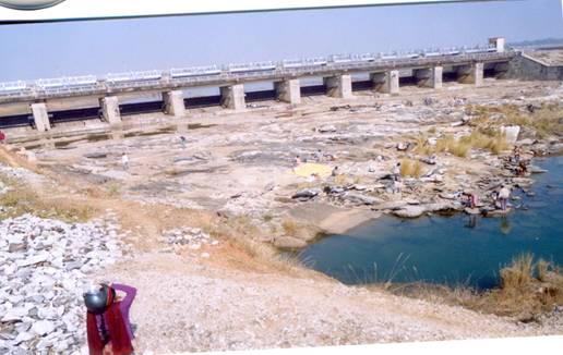
Photograph No.1
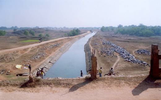
Photograph No. 2 Showing
Canal from
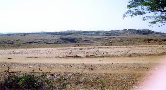
Photograph No. 3 Showing Granite Clan of the area
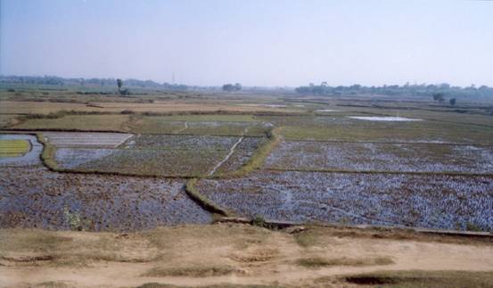
Photograph No.4 Showing Irrigation Method in the Area.
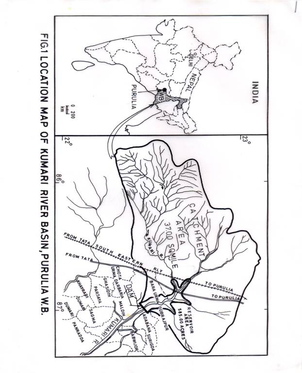
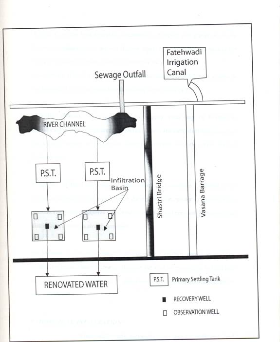
Fig. No.2 Plan view of the SAT experiment at Ahmedabad.
In this experiment municipal waste water was renovated to quality strands
significantly, better than obtainable by conventional secondary or biological
treatment procedures. The waste water renovation rates were-106 litres/day
and the system was continuously operated for -6 months.
(Gupta and Nema, 1998)
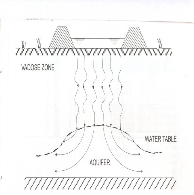
Fig. No.3. Section view through a typical infiltration basin with the arrows marking the subsurface movement of water through soil (vadose zone) and the underlying aquifer. The aquifer should be sufficiently transmissive to accommodate lateral flow of infiltrated water away from the recharge area without forming high groundwater mound that interferes with the infiltration process. (Bouwer, 2002.)